NOTE:Click on picture to enlarge. Click back button on your browser to return to this page.
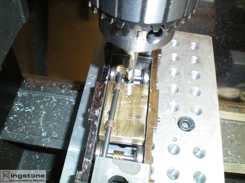 |
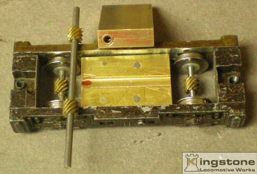
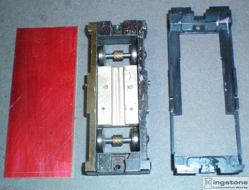
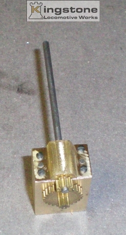
| I milled a slot down the center for the lower drive shaft with the helical gears on them. |
 |
| I was just going to make some small bearing caps that would fit over the top of the bearings to hold them down. |
 |
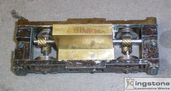
| Instead I made one large piece to hold the bearings in. |
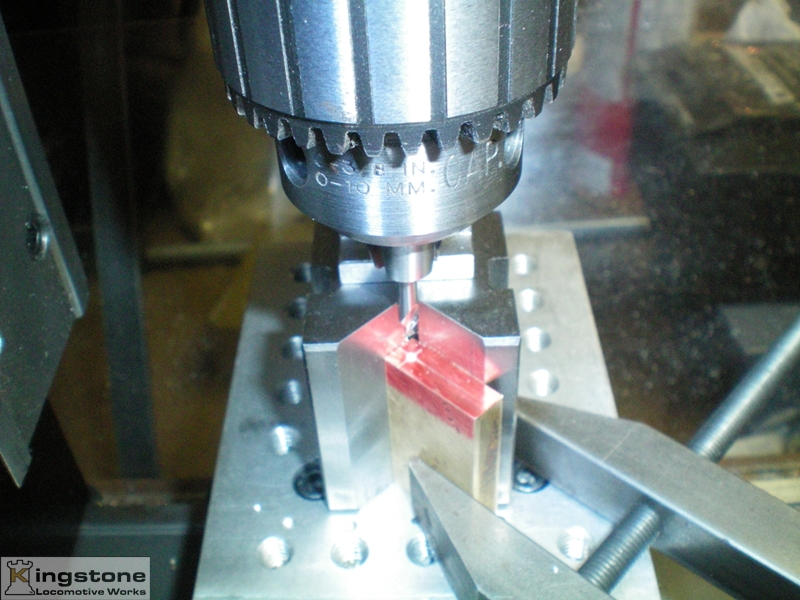 |
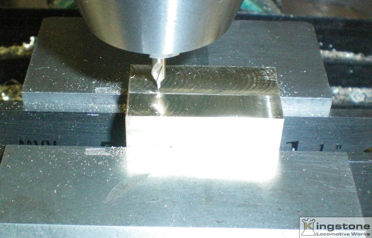
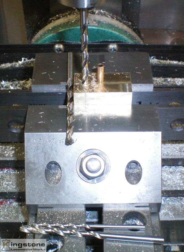
| I set up the Sherline mill with a small Vee block on it's side so I could drill the hole acuratley from both sides of the bearing block. |
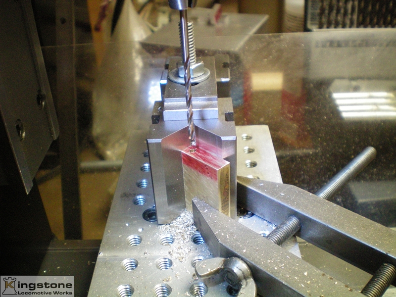 |
| Drilled to the final size of the bearing. The block has been drilled from both ends. |
 |
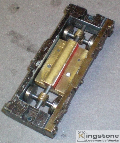
| The bearings pressed in the block. |
 |
| Test fitting to see if there is a good mesh of the helical gears. You don't want them to loose or to tight. |
 |
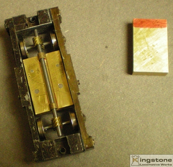
| The top part of the bearing block is trimmed down. Next will be the big gear on the shaft between the block and helical gear. |
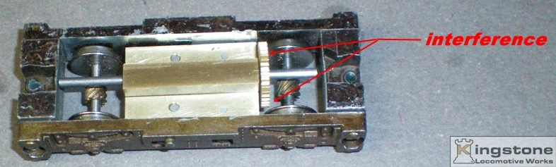 |
| And this is were I ran into a clearance problem. The gear doesn't really interfere with the one side (bottom arrow) but does were the top arrow is pointing to. The gear was hitting the wheel. Time for a redesign. |
 |
| I decided I would need a floor to suspend the gear tower off of. So a piece of 1/16" thick brass was cut out to replace the plastic floor/frame that was there. |
 |
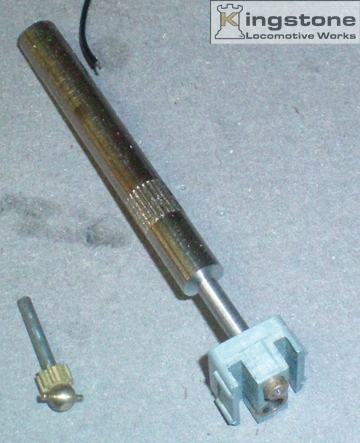
| This is the Hobby Town drive tower. I purchased a NWSL Motor that is shorter than the one I had originally planned on using. I was lucky, the motor shaft is the same size as the bearing of the first gear. The one with the ball on the end of it. The new tower and the rest of the gears are to the right of the motor. |
 |
| Next I made a mandrel to push the upper bearing out. |
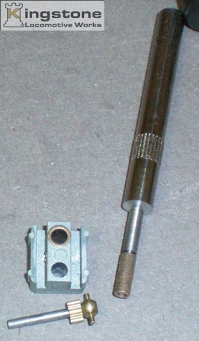 |
| Success. Got the bearing out with little effort. |
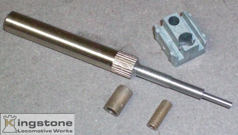 |
| Next I cut another step on the mandrel for the bigger bearing. Came out just as easy as the first. |
 |
| Now the bearings had to be mounted in the new gear tower. |
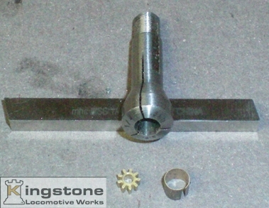 |
| But first I need to drill out the shaft for the top gear in the gear train. I tried pulling of the ball end off, but wound up snapping off the shaft. So I used a 1/4" collet from the Sherline lathe. I wrapped the gear with .005" shim stock because the gear was a very loose fit in the collet. I made sure that there was no run out and drilled the proper size hole. |
 |
| Next I made an upper bearing cap. This will give you an idea of how to keep it on the center line of the two parts. |
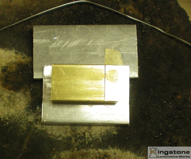 |
| The two parts ready to be soldered together. You need to make sure that they are kept in line. I made a small jig to hold the parts from some 1/4" thick aluminum plate and milled a step into it. Hard to see in this picture. |
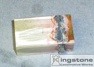 |
| The two parts soldered together ready for a little clean up in the mill. |
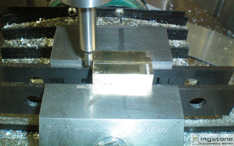 |
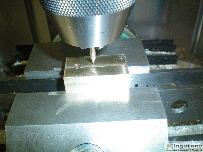
| After a skim cut on all four sides to clean up the part the edge was determined at the small part end that was soldered on using an edge finder. |
 |
| Once the edge was determined a move was made the thickness of the upper part. This puts the center drill right on the joint line of the two parts. This allows you to drill a round hole so when the two parts are separated you have two half's that the bearing fits in. This will become clearer in the next few pictures. |
 |
| I used four different size drills to sneak up on the hole size for the upper bearing. |
 |
| Worked great. A nice snug fit for the bearing. |
 |
| Next a move was made further down the tower for the next gear. You can make out the joint line on the first hole. You can see that the hole was drilled on the center line of the joint. |
 |
| And here's the end result of the holes drilled for the gears. A perfect fit to I might add. There is no binding of the gears. |
 |
| I then milled steps on both sides of the upper piece to a thickness of less than .062" for 0-80 screws that were only .125" long. I also drilled two 1/16" holes for line up pins. Here I'm tapping the 0-80 holes. |
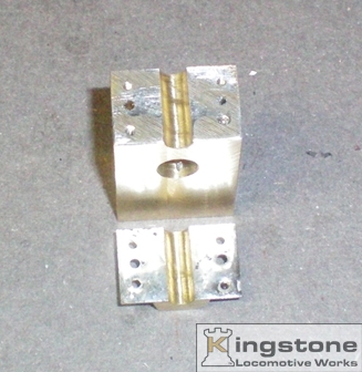 |
| After the drilling and tapping was done the part was heated to separate them. The surfaces were cleaned up with a file. Here you can get a better idea of the two half's that will hold the upper bearing. |
 |
| Here it is assembled with the two gears. |
 |
| And this is what it will look like once the motor plate is made and installed. Still a lot more work ahead on getting this in the small space of the engine. |
My idea of locating the drive shaft on the bottom plate of the frame didn't pan out. The gear tower
would have had to have
the bottom cut back more than I would have like. Instead I came up with the idea of mounting the last shaft of the gear
set in the tower itself. The next set of pictures will explain that procedure.