Upgrading a Mantua 0-4-0

This is the 28 pin DIP socket I use for male pins.


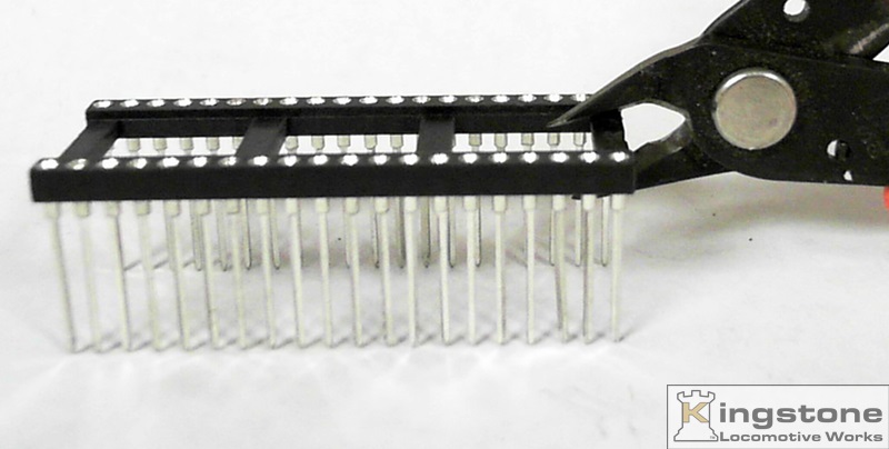
These are the 40 pin DIP wire wrap sockets I use for female sockets.


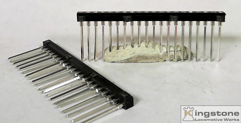
I cut the center bars out of the 40 pin DIP sockets.


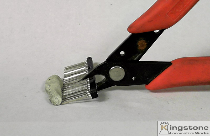
Then I cut off as many pins as I'll need.


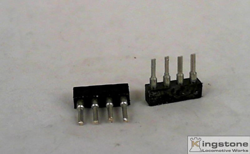
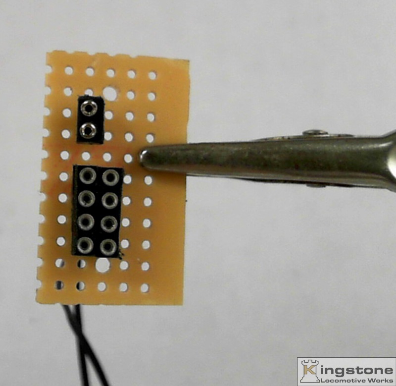
I'll need two 4 pin rows and one two pin row. The long legs are cut to the length I need.


Here they are just stuck into the perf board.


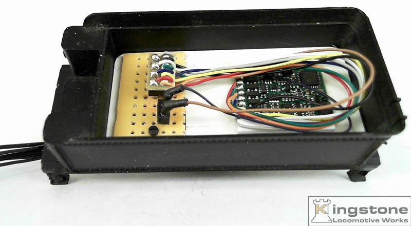
Here they are mounted on the sub-board for a test fit. The pattern is set for .100" square grid spacing. Pretty much
all circuit boards are based on a .100 square grid. The plug on the end of the decoder is set on a .100" grid spacing
and so is the perf board.


This is how I make my male pin plugs. I use the shorter version of the DIP sockets. The ends are round and fit
into the wire wrap sockets. The wire is tinned and stuck into the end and soldered in. Then a piece of heat shrink
tubing is placed over the pin and wire. I use wire from ribbon cale. They come color coded. Save time looking for
colored wire.


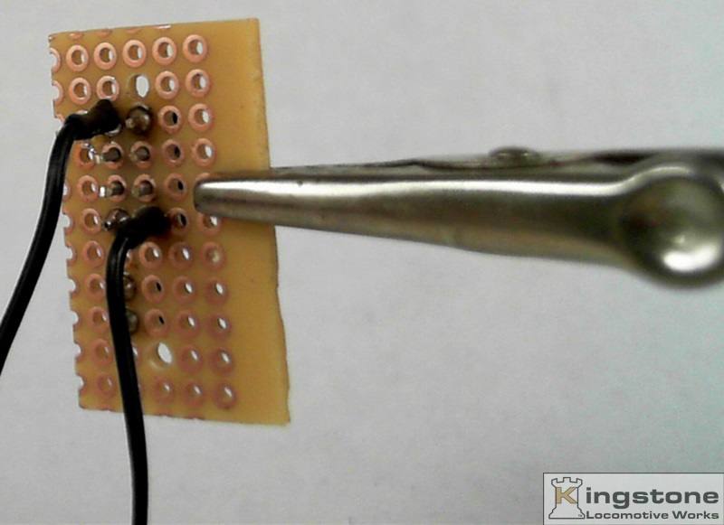
Here the wires that come from the wipers on the wheel have been soldered on.


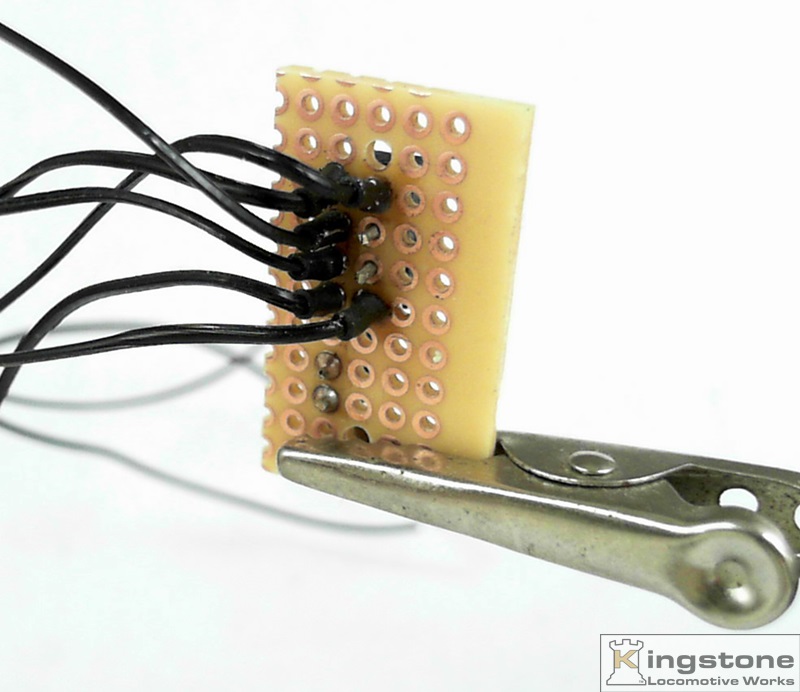
All the wires are needed have been soldered on. The wires will be "wrung" out when they get connected to the
engine. More on that when I get to that part.