![]()
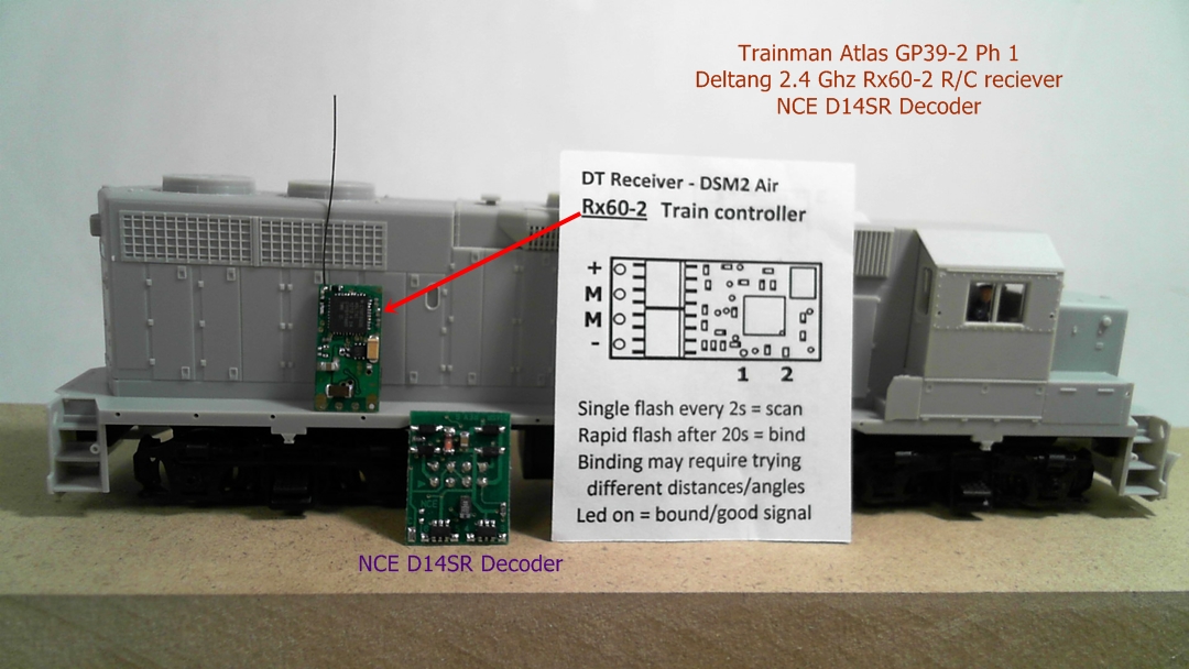
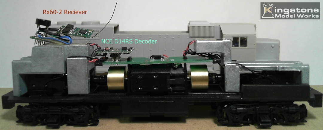
The GP39-2 Phase I and the two boards. On the left is the Rx60-2 and on the right is NCE's D14SR Decoder.
|
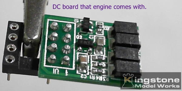
This is the board that the engine comes with and gets replaced if you are using a DCC decoder. The board is plugged into an 8 dip pin
for holding purposes.
|
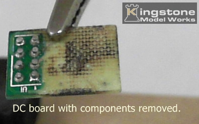
I removed all of the components by heating the board and shaking off the surface mount parts. I then sanded off
all copper traces on both sides. The pins
were left on to mount the bridge rectifier and motor wires.
|
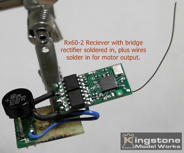
The ~ (AC) input wires were soldered to the incoming wires from the wheels and the motor wires were
soldered on to the pins going to the motor.
|
NCE D14SR decoder board installed.
|
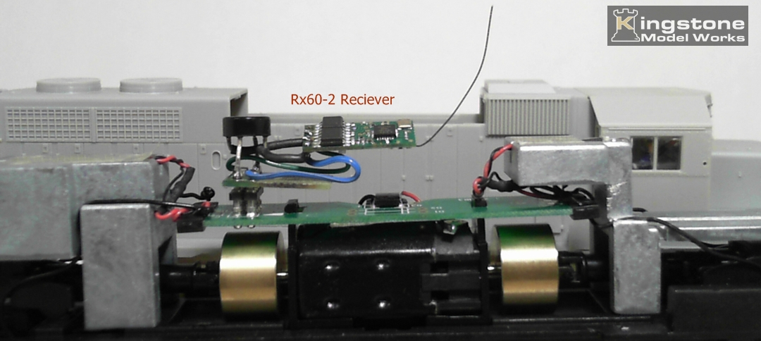
The Rx60-2 Radio Control board installed. Notice no modifaction needed to engine frame.
|
Video showing how easy it is to change from decoder board to modified Radio Control board.
I ran the engine to test how it worked and succeeded to blow the drive chips on the R/C board. Discovered that the engine will pull
approximately 5 amps. with the wheels spinning. The R/C motor drivers are only good for up to 2 amps. The project has been moth balled for now